The North
Penn ‘O’ Gaugers is a modular model railroad club
created for those who enjoy building and running ‘O’ gauge model trains
while
having an interest in preserving some of the rich railroading history
from the
Eastern Pennsylvania area. The club’s model railroad is based roughly
on a 40 -
50 year timeline between the 1930’s to the late 1970’s featuring
primarily, but
not limited too, equipment from the Reading and Pennsylvania railroads.
The club
meets several times a year at various locations to
setup, run and display its modular layout. A modular layout is a layout
that
can be disassembled and reassembled. The various modules are owned,
created and
maintained by each of the club members. Members are responsible to
bring their
module(s) to the display locations, help set up and then are able to
run their
own trains on the layout.
The modular
layout is designed to run using the Lionel TMCC
Legacy Command system.
MODULAR
STANDARDS
GENERAL
Each module
should meet the specifications as a minimum in order to provide the
necessary
interchangeability to allow the modular concept to work. Modules
constructed
per these instructions will allow mechanical and electrical
interconnection so
they can be arranged into various configurations permitting the
operation of
locomotives on either of the two mainline tracks or on the various
optional branch
line/siding tracks.
GENERAL
DIMENSIONS
Straight
Modular, The height
(thickness) of the frame and deck will be about 4”. A single basic
module shall
be 30” wide on both ends and 48” long. See
Figure A. A set of
modules
are allowed but must meet the dimension of 30” in width at each end of
the set.
The use of multiple modules in a set allows for greater flexibility of
track
routing. Intermediate modules can be of any length and width, (within
reason),
so long as the overall length of the set is exactly a multiple of 4
(four)
feet.
Corner Modular, a corner module
shall
fit inside a four foot square, 48” long by 48” wide. See Figure B.
FRAMEWORK
Frames to be constructed of 1x4 lumber. The boards should be
straight, solid and free of excessive knots and should be sanded
smooth. The
exposed edges of the framing material should be rounded (sanded or
edged with a
router) in order to minimize splintering and facilitate comfort during
the
handling of the module. The frame should be glued and screwed together
for
strength and it must be square and flat! Yellow carpenter’s glue is
preferred
to white glue.
PAINTING
All visible side surfaces,
including the ends of the module, will be painted a satin or semi-gloss
black.
The deck surface should be painted an earth tone brown before applying
road bed
or any scenery to protect it from water base diluted scenery adhesives.
MODULE LEGS
Each straight module shall have
four legs, corner module five, that are removable. Legs must have 3“
long
adjustment bolts (a carriage bolt) to allow for a total of 2” of
vertical
movement. (see Figure C) The adjusting bolt and corresponding T-nut
size may be
either 5/16th or
3/8th” diameter. The bolt should be completely threaded
over it’s full length. The exposed portion of the adjusting bolts are
to be
extended so that the top of rail of the two main lines shall be exactly
40
(forty) inches above the surface of the floor. With the deck and rail
heights
as described above, the leg length is 38”. This length should be
adjusted by
the difference between 3/8” and the actual thickness of the deck
material if other
than the preferred type. Locations for the legs are shown in Figures A
& B
for both straight and corner modules. The legs will fit into pockets in
each
location, as shown. Experience indicates legs that slide easily in and
out of
the pockets are preferred to a snug fit since dimensional changes in
wood
caused by high humidity could cause the leg to become stuck in the
pocket.
Recessing a T-nut on the inside center of the leg pocket will enable a
bolt to
be used to retain the leg in the pocket while the module is being
moved. A #4
screw eye may also be used.
CLAMPS
Two sturdy C-clamps, of at least 2
inch opening size, will be used to secure the modules together during
setups.
Two clamps shall be provided with each module by owner.
MAINLINE
AND BRANCHLINE TRACKS
MAINLINE TRACKS
The two mainline tracks shall be Atlas ‘O’ 21st
Century Track System with traditional plastic simulated wood ties. The
mainline
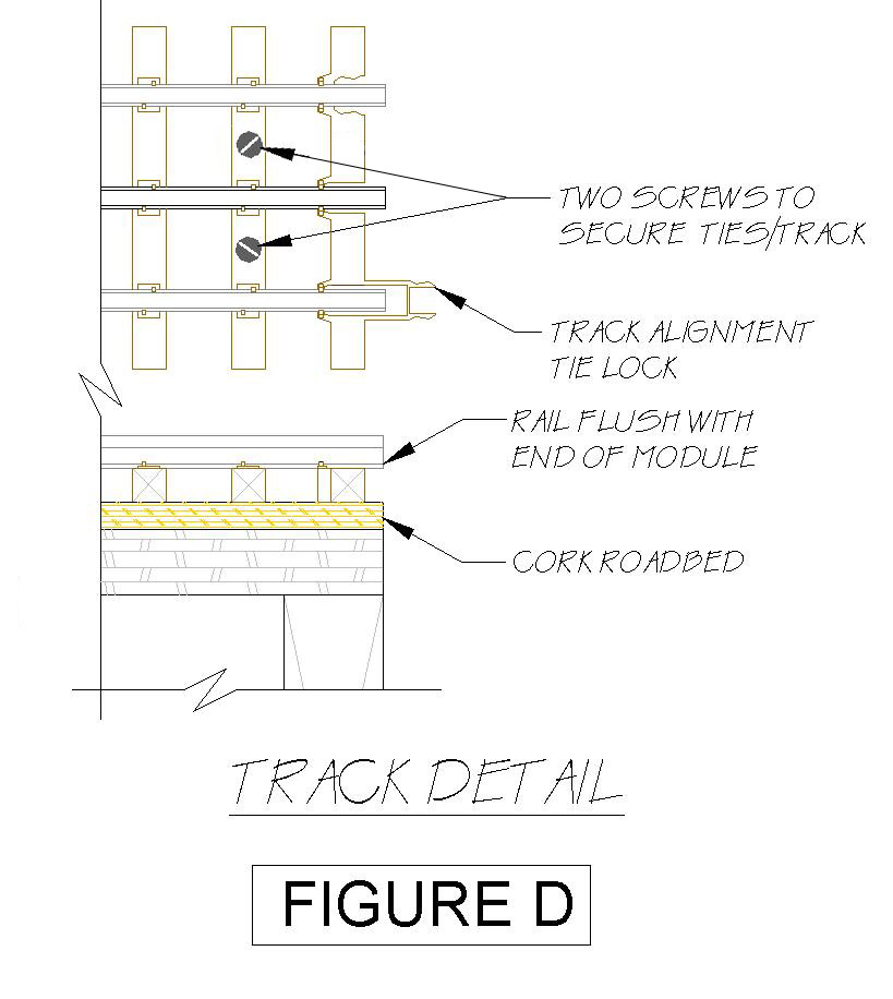
tracks are to be secured (glued, screwed or
nailed) onto standard ‘O’ gauge cork roadbed. The
roadbed should be
glued to the surface of the module in lieu of nailing to help ensure
the
roadbed remains flat (all-purpose white glue or caulking adhesives are
suggested). The roadbed should be painted grey, similar to the shade of
grey
used for the ballast. Curves are permissible and shall be a minimum of
O-72
(36” radius). Corner modules will use O-81 (40.50” radius) for track 1
and O-72
(36.00” radius) for track 2.
Track
Spacing The double track mainline will have a spacing exactly
4 ½” on center. Track 1 centerline exactly 4” from module front
edge. Within a
module or multiple module set, the track centerline may be different
and may
have curvature as long as the track centerlines at each end of the
module are
set exactly as standard. The mainline track/rail at the end of each
module
shall be straight, parallel and flush with the front edge of the
module, 90
degrees from the module end (see Figure A & B) and be screwed down
through
the last 2 track ties as shown in figure D. Track tie lock should be
intact to
help with final track alignment. Rail joiners are not required between
modules
but extra attention shall be given for the close track location
tolerance.
MAINLINE
TURNOUTS
Turnouts on the mainline shall be a minimum of O-72 turnouts
recommended from Atlas or Ross Custom Switches. All turnouts may have
manual or
electrical switch throws. Turnouts between the mainline tracks shall
have the
center rail insulated to keep each of the mainlines electrically
isolated.
MAINLINE BALLAST
The ballast used on the mainlines shall be Woodland Scenics
Gray Blend Coarse Ballast # B1395.
BRANCHLINES
Branchlines shall be Atlas ‘O’ track. Cork roadbed need not be used but
transitions
are necessary to change from the elevation of the mainline tracks to
the
branchlines. Turnouts shall be a minimum of O-54 turnouts but a minimum
of O-72
is preferred. Any ballast may be used for branchlines. Any
branchline/siding
turnout from the mainline tracks shall have the center rail insulated
to keep
each of the mainline tracks electrically isolated.
ROUTING
CONVENTION
Right hand running shall be the routing convention for
locomotives on the mainline. In looking down the track in the direction
of
travel, the engine will operate on the right track. The two mainlines
are
designated as “North to South” and “South to North”. The mainline track
(track
1) on the outside is S to N(northbound) and the track on the mainline
inside
(track 2) is N to S (southbound).
WIRING
AND CONNECTIONS
GENERAL
Each
module will provide mainline power busses and connectors in order to
provide
said power on a continuous basis throughout the display. The
interconnected
layout is designed to be powered from a single location. (see figure E)
POWER SUPPLY
The
power for the club layout comes from the Lionel ZW-L transformer.
This advanced transformer provides the
power needed
for operating the club layout with a full 720 watts of power,
all within a single unit. This modular layout is designed to
run primarily as command control but this transformer allows the
capability of running conventional locomotives with the Legacy
remote
without the use of additional TPC’s and such.
POWER BUS CONNECTORS
Each module should have an electrical bus running its length
consisting of six (6) wires of 12 gauge stranded wire. 16 gauge
stranded wire
shall be used for the drops from the track to the bus.
The electrical bus for each module
will be connected to the adjoining module using ‘Anderson Power Pole’
30 amp
connectors
Connector wiring assignments:
1 = Mainline Track 1 Power, Red, ‘A’
2 = Mainline Track 2 Power, Red, ‘D’
3 = Branchline Track Power, Red, ‘B’
4 = Accessory Power, Red, ‘C’
5 = Ground “U” (common for all tracks), Black, ‘U’
6 = Earth Ground, Green
All bus
wires shall have their wiring assignment numbers labeled a minimum of
three
location within each module.
TRACK POWER
Each main line on the module should be connected to the bus
around the middle of the module.
Track
power shall not be used to power accessories, such as electric switch
machines,
lights, or other powered devices.
ACCESSORY POWER
Accessory
power is to be used for switch machines, lighting and signals only. Any
other accessory
(such as motorized accessories) should be powered by a separate power
supply
provided by the individual module owner.
SCENERY
GENERAL
The overall design, motif and
scenic details are optional to each module builder. Each module can be
designed
as a diorama within itself, or it can be planned to merge with other
modules in
the layout at the discretion of the module builders.
GROUND COVER
All grass, ground cover, and foliage will be in appropriate
shades with no bright toy-like colors in appearance. Autumn foliage is
permissible. Trees, tall shrubbery and other such ground cover shall
maintain
proper clearances so as not to interfere with any train operation. Any
module
surface not covered with scenery materials should be painted a muted
earth tone
brown.
SKYBOARDS
Each module will have a removable skyboard that extends 12”
above the full width of the module surface. Care should be exercised to
keep
gaps between adjacent skyboards to a minimum. Each skyboard will be
1/8”
Masonite with an overall width of about 16”, and will be painted with a
sky
blue paint. Use Sherman Williams #SW1787 Baby Blue or #BM 33-4 Universe
Blue on
the viewers and a satin or semi-gloss black on the back. The rear edge
scenery
will be blended into this neutral sky background as appropriate. If you
use a
carrying handle on the back of the module, you will need to notch the
skyboard
accordingly. The skyboard will be attached to the back of the module
with
strong clamps, bolts & washers, or other appropriate means to
secure it
firmly in place.
FASCIA BOARDS
A masonite fascia board may be provided on the front of each
module. The fascia will be the same height as the top of the deck for
the first
three inches from each end of the module. The area in-between these
points can
be of any height (within reason) required to effectively blend into the
overall
landscape of the module. The fascia board should be securely fastened
to the
module using flat head screws which will be covered by the skirting.
The
viewer’s side of this fascia should be painted a semi-gloss or satin
black.
SKIRTING
Skirting is attached to the fronts of the modules at
public displays for “dressiness”. It is held on with VELCRO, thus each
module
must have a strip (1/2” wide is OK) applied to the front along the top
edge.
The hook side must be attached to the module so that the top edge of
the Velcro
meets the bottom of the module deck. The skirting is provided by and is
the
responsibility of the club.
ADDITIONAL ITEMS
Prebuilt Module
Framing
Straight modular framework sections that have already been
built per club standards are available, ask about pricing. They do not
include
paint, track or scenery. This is a great option to help get you
started. This
first step, the basic construction stage, is often the obstacle that
prevents
many from getting started.
Club Discounts
Being a member of the North Penn O Gaugers does have some
cost saving privileges from our sponsor Henning’s Trains in Lansdale.
Members do receive a discount on various items purchased through their
store.
To receive such discounts simply show your club membership card at
checkout.
Discounts
include,
15% off all Atlas track products.
10% off all GarGraves track products
10% off all Lionel products (excluding locomotives)
5% off all
locomotives.
10% off all scenery products and buildings.
10% off all books & videos.
Discounts
for club members
only, limited to in-stock items.
Does not include used or consignment items.
Membership Fee
$24.00 for the first year, $12.00 for each year there
after. Membership fee is used to help
cover
costs of items such as layout skirting, promotional materials, setup
location
expenses, power supply, etc.
Contact Information
For information about the club contact Bill Henning
Email: bill@henningstrains.com
Phone: 215-362-2442
Web: www.henningstrains.com/NPOG
Other
Club Info.
Liberty Hi-Railers
The Liberty
Hi-Railers is an O gauge hi rail
modular railroad club.
They are a group of model
train enthusiasts who simply enjoy having
fun while running
trains. The club meets at train shows through the
year to display their modular
layout.
Web: www.liberty-hi-railers.com
John Devlin, Email: jdevlin42@comcast.net
Bill Parkinson, Email: bill_parkinson@yahoo.com

North
Penn S Gaugers
The North Penn S
Gaugers is a modular club established in 1998 to
encourage S gauge model railroaders
in the
North Penn area. They
welcome both S scale
modelers and American Flyer operators and
collectors to their
group.
Alex Larkin, Email: alexj42sflyer@comcast.net